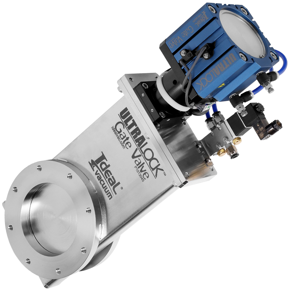
Solenoid Kit for UtraLock Pneumatic Gate Valve, 24 VDC, Includes Mounting Hardware.
This solenoid kit is for use with an Ideal Vacuum ULTRALock
TM or HVA pneumatically operated gate valve. The solenoid operates the gate valve's pneumatic piston. All fittings and connections must be leak-tight to ensure proper operation.
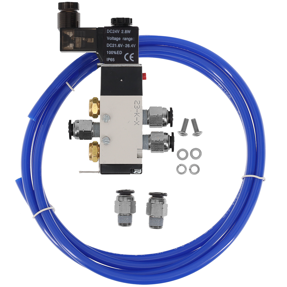
These 24 VDC solenoid kits include an AVS-5111-24D, 4-way, direct-acting solenoid valve, and everything else needed to operate an UltraLock or HVA pneumatic gate valve including air line tubing push-to-connect fittings. For faster actuation of larger gate valves, larger tubing and different push-to-connect fittings may be used.
Kit Components:
- AVS-5111-24D 4-way solenoid valve.
- Mounting bracket for use with Ideal Vacuum UltraLock or HVA pneumatic gate valves.
- All necessary mounting screws and hardware for use with UltraLock pneumatic gate valves.
- Five (5) 4 mm OD tubing push-to-connect to 1/8" male universal pipe thread adapters.
- Two (2) exhaust mufflers.
- 6' length of 1/4" OD flexible polyurethane tubing.
Solenoid Valve Features:
- 24 VDC, 2.5 W.
- 20-115 PSIG working input pressure. 215 PSIG max input pressure. 80 PSIG required for most pneumatic gate valves.
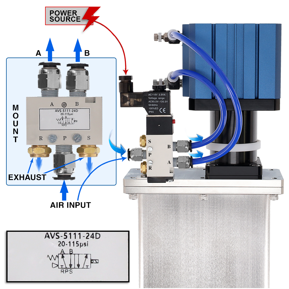
- Five (5) 1/8" NPSF ports:
- A: Normally open outlet to P. Exhausted to A when energized.
- B: Normally exhausted outlet to R. Open to P when energized.
- P: Inlet.
- R: Normally closed. Exhaust from A when energized.
- S: Normally exhaust from B. Closed when energized.
- Locking manual override button.
- Din style wiring connector with LED indicator.
- Buna rubber seals.
When properly connected, if there is an interruption to the solenoid's electrical power, the attached gate valve immediately closes and remains in the closed position until power is restored.
The solenoid valve has a red manual override button. When properly connected, pushing the overide button forces the gate valve to open. When the override button is released the gate valve closes. The override button may be locked in the pressed position using a flat head screw driver and rotating the button 90°. Rotating the button back to its original position will allow it to spring back to the unpressed position.
Installation Instructions:
- Mount the solenoid on to the gate valve bonnet using the included mounting bracket and screws. When no tapped holes are present, the solenoid must be mounted remotely.
- Attach air line tubing between solenoid port B and the gate valve's port which opens the gate valve when pressurized (the port closest to the bonnet).
- Attach air line tubing between solenoid port A and the other gate valve port which closes the gate valve when pressurized (the port at the top of the pneumatic cylinder).
- Optionally connect solenoid ports R and S to house exhaust.
- Attach solenoid port P to (user supplied) house air at 80 psi.
- Apply 80 PSI air pressure to the solenoid valve and verify that the gate valve closes and remains closed.
- If the gate valve opens and remains open, switch the tubes to solenoid outlets A and B.
- Press the manual overide switch and verify that the gate valve opens and remains open while the switch is pressed.
- Release the manual overide switch and verify that the gate valve closes again.
- With no electrical power applied, the solenoid will automatically be in the closed, locked position . When electrical power is applied to the solenoid, the gate valve will open.